| Editor’s note: The IAFF and the USFA released an updated version of its Voice Radio Communications Guide for the Fire Service in Oct. 2008. The guide focuses on seven sections of communications – basic radio communication technology, radios and radio systems, portable radio selection and use, trunked radio systems, system design and implementation, interoperability, and radio spectrum licensing and the federal communications commission. |
Several different types of radios are used in the fire service. These radios can be classified as mobile, portable, or fixed; analog or digital; and direct, repeated, or trunked radios. In this section we discuss the operation of these types of radios, and the features, benefits, and problems associated with their use in the fire service.
Mobile radios are designed to be mounted in vehicles and get their power from the vehicle’s electrical system. They can be of either a one- or two-piece design, with the radio itself separated from the controls. An external antenna is connected to the radio and permanently mounted to the vehicle. Mobile radios usually have better performance than portable radios, including better receivers and more powerful transmitters. Mobile radios used in trunked radio systems may or may not have more powerful transmitters because the systems are designed for portable use, reducing the need for high-powered transmitters.
Portable radios are hand-held radios powered by rechargeable or replaceable battery packs. They usually have an external rubber antenna attached to the top of the radio.
Mobile and portable radios have similar controls to perform their essential functions. These include things such as changing channels, adjusting the speaker volume, and transmitting. The common names for these controls are the channel (or talkgroup) selector, volume adjustment, and push-to-talk (PTT) switch. Some radios, particularly those intended for fire and police use, will have an orange or red EMERGENCY button. This button may be programmed to indicate to the radio system, and to other users, that a user has an emergency. Older radios may have a squelch adjustment knob, but most modern radios have internal control settings or adaptive squelch so that a squelch adjustment knob is no longer necessary.
Base station radios are located at fixed locations, and usually are powered by AC utility power. Base stations generally are higher in performance than mobile and portable radios, with higher-powered and more stable transmitters and more sensitive and interference-resistant receivers. Some fire departments equip fire stations with base station radios to provide enhanced coverage throughout their service area and to provide backup communications in the event of a primary communications system failure.
Repeaters are similar to base stations, but they can transmit and receive at the same time, retransmitting the signal received by the receiver. Repeaters are used to extend the coverage of portable or mobile radios.
Radio console equipment is used by dispatchers to control base station radios and repeaters and allow the dispatcher to receive and transmit on one or more radios simultaneously. The consoles typically have individual volume and transmit controls for each radio as well as a master volume and transmit control. Headsets can be connected to the consoles along with footswitches, allowing dispatchers to operate the console hands-free so they can operate computer equipment simultaneously.
Analog Radios
The human voice is an analog signal; it is continuously varying in frequency and level. Analog radios have been in use since the invention of voice radio in the early 1900s. The type of analog radio used today was invented in the 1930s to improve on the older radio’s poor immunity to noise. These radio systems use frequency modulation (FM) to modulate the transmitted signal with the user’s voice. The main advantage of FM over older radio system types is that FM radios tend to reject (interfering) signals that are weaker than the desired signal.
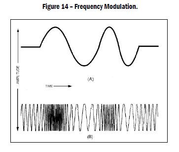
Analog FM radios operate by causing the transmitting frequency of the radio to change directly with the microphone audio. Initially the signal is filtered to remove any frequencies above human voice, but no other changes are made to the signal. Figure 14(A) shows an example signal from the microphone, and Figure 14(B) shows the resulting change in frequency of the transmitted signal.
|
FM radios constantly have a signal at the output of the receiver, and a squelch circuit is used to mute the output of the radio receiver when no desirable signal is present. Noise squelch circuits mute the output as long as only squelch noise is present. Most older radios feature adjustable squelch level controls, allowing the user to make the radio less sensitive if there is interference. However, most new radios have improved receiver performance and have fixed squelch levels or levels that are adjustable only by radio technicians.
To further reduce received noise and interference, well-designed analog radio systems use tone-coded squelch (TCS) or digital coded squelch. TCS is also known by its Motorola trademark Private Line™ or PL and by its GE (now M/A-COM) trademark Channel Guard™.
TCS systems mix a subaudible tone with the audio from the microphone and transmit the resulting signal. When a radio receives a signal with tone-coded squelch, the TCS decoder attempts to match the tone present in the received signal with the desired tone. If the correct tone is present, the receiver is unsquelched and audio is routed to the speaker.
Digital Radios
To improve audio quality and spectrum efficiency, radio manufacturers introduced digital radios. This was a necessary move based on the FCC requirements to continue narrow banding. Since being introduced, digital modulation has been touted as having more user features, better audio clarity, and higher spectrum efficiency than analog modulation.
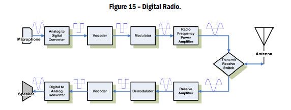
In the digital world when a user speaks into the microphone the radio samples the speech and assigns the sample a digital value. A vocoder (voice coder) or codec (coder/decoder) in the radio performs the function of converting analog voice to a digital data packet. The digital data packet can vary in the number of bits. The higher number of bits in the data packet, the higher the level of precision. Numerous samples are taken each second to reproduce the source audio. The higher sample rate per second and number of bits per sample result in increased audio quality. For example, compact disc (CD)-quality audio samples 44,100 times per second and the number of graduations in the sample is 65,536. The use of digital audio was expected to reduce static and increase the range of radios in weak signal conditions.
|
Digital Audio Processing
A vocoder in a digital radio converts analog voice to a digital interpretation from an audio sample. Digital radios, unlike CD or DVD audio, have very limited data rates. Even cell phones have higher data rates than a digital radio. Because of limited data rates, digital radio audio is sampled at a much lower rate with less precision. Designers of the portable radio vocoders felt the radios did not need the same level of precision as CD-quality audio, since reproduction of human speech was the goal.
This is a basic explanation of how analog voice is processed by the radio.
Transmitting radio:
1. The user speaks into microphone.
2. The audio is sampled and converted to a digital interpretation by an analog to digital converter (A/D converter).
3. The vocoder converts the digitized speech into digital data.
4. The modulator modulates the radio frequency (RF) with the digital data.
5. The modulated RF signal is boosted in power by transmitter amplifier.
6. The signal is transmitted from the radio antenna.
Receiving radio:
1. The modulated RF is received by antenna.
2. The received RF signal is boosted to a useable level by the receive amplifier.
3. The signal is demodulated by a demodulator. This removes the RF component of the signal leaving the digital data component.
4. Digital data is decoded by the vocoder into digitized speech.
5. Speech data is converted to an analog signal by a digital to analog converter (D/A converter).
6. Analog is sent to the speaker.
|
Analog versus Digital Signal Variations With Signal Strength
As the radio user travels further from the transmitting radio, the signal strength decreases. The signal strength directly affects the ability of the radio to reproduce intelligible audio.
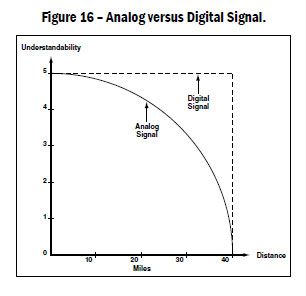
In an analog system, the clarity and intelligibility of the transmission, as received by the user, decrease directly as the signal level decreases. The noise (static) in the signal progressively increases in strength, while the desired signal decreases, until the transmitting user cannot be heard over the noise.
When a digital user transmits to a receiver, the transmitted signal decreases just as the analog signal does. However, the error correction in the digital transmission contains extra information that allows the audio information to be heard even with a large decrease in signal level. As the receiver travels further from the transmitter, the signal level decreases to the point where the error correction cannot correct all errors in the signal. When this point is reached, the receiving users will hear some distortion in the signal and may hear some strange nonspeech noises. These strange nonspeech noises are sometimes called “Ewoking” after the language spoken by the Ewok characters in the movie “Star Wars”. Once this point is reached, a small reduction in signal level will cause the number of errors to exceed the ability of the system to compensate, and all audio will be lost.
|
The problem this causes is that the radio signal goes from usable to unusable with little or no indication that this is about to occur. Figure 16 shows that, with an analog radio system, the signal slowly gets noisier, giving the user hints that the signal is getting weaker. This behavior adds to the situational awareness of the user and allows him/her to make decisions about the environment. Although digital radios provide a larger range of usable signal levels, the lack of advance indication of signal level decrease allows users to get closer to complete loss of communication without any advance warning. Some radio manufacturers have indicated they would develop solutions to this problem; however there are no solutions implemented in current production radios.
APCO P25
The Association of Public Safety Communications Officers (APCO), representing the public safety technical community and the Telecommunications Industry Association (TIA), recognized there would be a requirement to move to digital technology. This provided an opportunity to develop an open standard that would allow different manufacturers to build equipment that could operate together. The goal was to introduce competition into the market, help control costs, and provide a technology platform for improved interoperability.
Up until the development of this standard, each manufacturer had proprietary digital radios that could interoperate only with like radios. Working with the TIA, APCO coordinated the work of manufacturers to develop the P25 Standard for digital radios. Modern public safety digital radios use this standard. P25 is the national standard for public safety digital radios, but also is backward compatible for analog use. This standard was developed to allow radios from multiple manufacturers to communicate directly using a common digital language, define standards for trunked radio systems to allow multiple manufacturers to operate on a common platform, and to provide a roadmap for future features and capabilities.
What P25 is Not
P25 does not address any operational or interoperability needs. P25 does not provide a fire department with interoperability unless it is planned for. A lone agency on P25 is no more interoperable than being on a UHF system trying to interoperate with a department on VHF. P25 only provides manufacturers with a common digital language for the radios and system infrastructures.
P25 system standards also were meant to allow radios of different manufacturers to operate on any other P25-trunked radio system. This has not been the case to date. System manufacturers were allowed to develop proprietary features within the P25 standard. This has resulted in an “open architecture” that isn’t as open as intended. This is especially true in large, complex multizone trunked systems, where complex proprietary roaming schemes are used to allow radios to operate over large geographic areas.
P25 Characteristics in High-Noise Environments
When P25 is used in settings where the background noise level is within limits set in the P25 standard, it provides useable audio. However the P25 vocoder was not designed to operate in the high-background-noise environments encountered on the fireground. When the P25 vocoder was being developed, the designers tested intelligibility of the digital audio with high ambient noise levels at the receiving radio. The P25 vocoder is unable to differentiate the spoken voice from the high background noise and assigns a digital value that does not accurately represent the voice. The result is unintelligible audio or broken audio with digitized noise artifact. Users of P25 radios have been affected by many common fireground noises. The SCBA and alerting systems for low-air or inactivity and PASS (Personal Alert Safety System) devices have made the audio transmitted from digital radios unusable. P25 radios transmitting from high-noise environments do not perform to the same levels as analog radios.
Self-Contained Breathing Apparatus Mask Effect on Communications
The effect of SCBA masks on the human voice has been studied by the Institute of Electrical and Electronics Engineers (IEEE).
The IEEE tests were performed to find the effects of the SCBA system on voice intelligibility. Tests were performed with no SCBA mask and with an SCBA mask, with analog audio and digital audio. Participants wearing the SCBA masks read standard word recognition sentences while the listeners recorded what they thought they heard. As you will note in the table below, digital word error rates (WER) were always higher than analog error rates. Digital in Mask A had an average WER of 12.5 percent and digital in Mask B had an average WER of 6.8 percent. All of these tests were performed in a sound studio with no background noise. In an actual firefighting situation, the WER likely would be higher. Tests were also performed with the SCBA low-air alarm from each manufacturer in operation. In these tests the WER averaged 18.7 percent in analog and increased to 64.4 percent in digital.
|
P25 Digital for Firefighting?
Fire departments around the country have reported difficulties with digital radios, and studies performed by National Institutes of Standards and Testing (NIST), the International Association of Fire Chiefs (IAFC), and portable radio manufacturers have supported the findings from the field users. Based on the experiences of fire departments using digital radios and the studies in response to these problems, the International Association of Fire Fighters (IAFF) has taken a position that does not recommend P25 digital portable radios for fire-fighting applications where the firefighter is using an SCBA.
These studies cite decreases in the ability of the firefighter’s voice to be translated into a digital signal by the P25 radios. When fireground noise is introduced, the voice translation ability of the P25 radio provides decreased to no intelligibility. These problems are worsened when the firefighter is speaking into the portable radio through an SCBA facepiece, with or without a microphone inside the facepiece. Bone microphones or throat microphones may minimize the interference caused by background noise but are impractical for most firefighting portable radio uses. Speaker microphones are subject to the same problems that are found with the microphone on the portable radio.
The configuration of the P25 vocoder is limited in its capability to translate the human voice in the presence of common fireground noise or through a facepiece. This can pose a safety hazard for fireground operations. To maintain safety, fire departments should consider using portable radios that incorporate analog modulation for operations where the firefighter is using an SCBA.
Radios using the P25 digital technology have performed well for other fire service functions, such as on emergency medical incidents, support functions on the fireground where an SCBA is not required, and law enforcement operations. The difficulties presented by the inability of P25 radios to produce intelligible voice messages in the presence of fireground noise is a significant safety concern and should be considered seriously by public safety radio system designers and users.
The communications industry is aware of the present operational problems with P25 vocoders. If this issue is addressed and corrected by the industry, future P25 radios may be suitable for firefighting operations. Another area of opportunity for improvement is for the portable radio function to be more completely integrated into the SCBA. This integration may lessen the impact of background noise on the vocoder.
Direct and Repeated Radio Systems
Radios communicate when the transmitter sends out a signal that is received by one or more receiving radios. When the signal is received from the radio initially transmitting the signal, the communication is direct (i.e., there is no intervening radio or system). One radio transmits, the other radios receive, and this type of communications also is known as simplex communication.
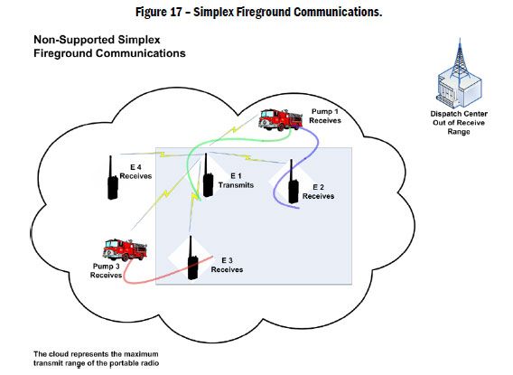
Nonsupported Simplex Communications on the Fireground
Using simplex communications maintains positive communications between the IC, exterior onscene units, and interior units without the reliance on exterior communications systems. Maintaining positive communications is especially important in “Mayday” situations. When users on simplex radios are deployed to the interior of a structure they create a radio receiver network. As more and more radios move into the structure, the strength of the network increases. If Engine 1 calls Mayday, the probability of another radio on the interior receiving the transmission is high. If the Mayday is not heard by the IC, another radio operator on the interior can act as a human repeater to repeat the message to the IC. In addition, the number of radios in a structure creates redundancy, where reliance on a single repeater or trunked system creates a single point of failure. Simplex communications allow direct communications with the initiator of the Mayday and other crews on the fireground.
In this example, the simplex communications are not supported. This means that there is no infrastructure to support transport of the fireground communications to the dispatch center. When the radios involved in direct communication are portable radios, the communication distance typically is limited to a few miles; for mobile radios the distance can be 50 to 100 miles. Often this is referred to as “line-of-sight communication” and this makes direct radio communication most suitable for use by units on an incident scene.
|
The direct communication method is the simplest form of radio communication and is easily affected by terrain blocking. If a mountain or other obstruction is between the transmitting and receiving radios, communication may not be possible. However, the short-range nature of direct communication also allows the radio channel used by one communicating group to be reused by another group further away. If the second group is far enough away that it does not hear the first group’s communications, then the channel can be reused. This minimizes the number of channels needed by an agency.
When a radio system must cover a larger area, or when terrain or other obstructions limit the distance a system can cover, additional equipment is needed to overcome these limitations.
Receiver Voters — Improve Field Unit to Dispatcher Communications
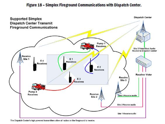
Dispatch centers connected to high-powered transmitters provide the dispatch center with talk-out capability. Transmitters are elevated to achieve better line-of-sight communications with the service area. High-powered transmitters ensure that the dispatch center transmissions are heard throughout the service area and provide some level of in-building coverage. See Figure 18.
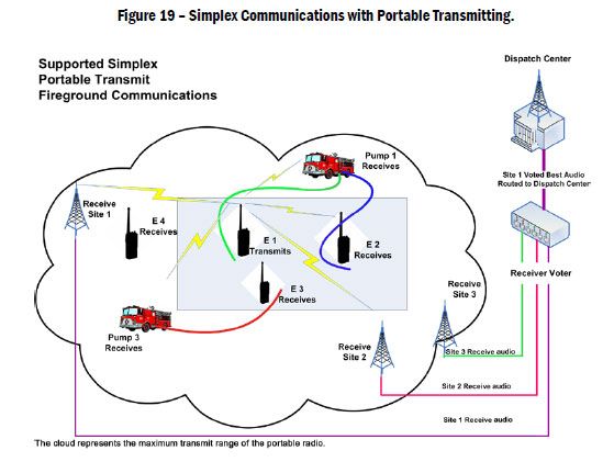
Portable radios have limited power and cannot always transmit a signal strong enough to reach the transmitter sites. To provide a more balanced system, receivers are networked together throughout the service area in a receiver voter system (RVS). Comparison of the received audio signal takes place in a receiver voter. The receiver voter and its network of receivers are referred to as the RVS. The RVS usually is located at the dispatch center. The receiver voter compares the audio from all receivers and routes the audio from the receiver with the best audio quality to the dispatcher. This type of system provides very reliable fireground communications and supports fireground simplex channels.
|
|
Repeaters — Improve Field Unit to Dispatch and Offscene Units
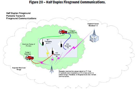
Receiver voters are one solution to get communications from a radio user to the dispatch center, but another solution is needed to get the communication to other radio users. One type of system that can solve this problem is a repeated radio system. Repeated radio communication, also known as half duplex communication, uses two radio frequencies for communication. The transmitting radio transmits on frequency 1 (F1), and that signal is received by the repeater. The repeater then repeats the transmission on frequency 2 (F2), and this signal is received by the receiving radio. By locating the repeater on a high building or mountain, the range of transmissions from the transmitting radio can be more than doubled, and can reach over obstacles effectively.
Another solution to improving communication between field units inside buildings or tunnels and dispatch and offscene units is the bidirectional amplifier (BDA). BDAs can be used with half duplex radio systems to extend coverage from inside the structure to the outside of the structure and vice-versa, but BDAs do not operate with simplex radio systems. BDAs are discussed in more detail in Section 5—Trunked Radio Systems.
|
The significant operational difference between direct and repeated communications systems affects units operating at an incident scene. With direct communication, the transmitting radio’s signal only needs to reach other radios directly on the incident scene. With a repeated system, the signal must reach the closest repeater location, which may be much further from the incident than the receiving radios.
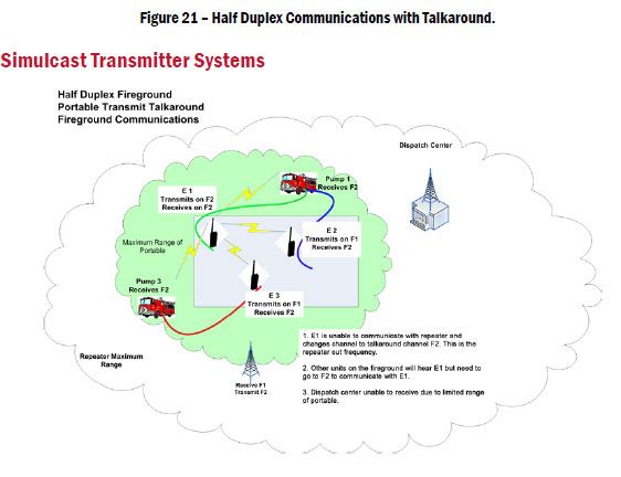
Figure 21 on the next page, shows a method to overcome this limitation. If unit E1 is unable to communicate with other units on the fireground using the repeater system, E1 can switch to talkaround mode on the radio. This mode allows the unit to transmit in direct mode to other radios on the fireground and receive from the units in either direct or repeated mode. Since the radio is not able to reach the repeater, the dispatch center cannot hear the radio, although other radios on the fireground can hear the unit. A unit that switches to talk-around should announce this immediately so other units know that they also may need to switch to communicate with the isolated unit.
|
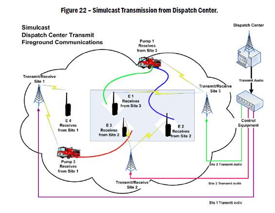
When a radio system must cover a large area, but the number of available frequencies is limited, a simulcast transmitter system may be the solution. With this system, multiple transmitters simultaneously transmit on the same frequency. The transmitters must be precisely synchronized so that the signals they transmit do not interfere with each other. In addition, the audio source sent to the transmitters must be synchronized so that the radio user hears the same signal from each transmitter. The system consists of a simulcast controller and two or more simulcast transmitters. The advantages of a simulcast system are the coverage of a large area, with high signal levels throughout the area, while using only a single frequency.
|
Operational Considerations
Communication needs on the fireground can be categorized based on the position in the Command structure. The military operates in a similar manner and is used here to illustrate the concept.
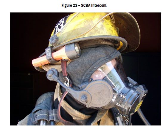
In a military theatre of operations, there are distinct communication requirements based on position in the Command structure. At the lowest level are individual team communications. This level of communication is for command and control of the team members to accomplish a task. Like the fire service, these communications are often simplex communications and short range. An example of this would be communications over a SCBA intercom—a short-range, low-power radio designed for communications among a single company or crew.
|
Next is the tactical level, where the tactical Command element is communicating with multiple teams to accomplish the tactical objective. This level requires communications with enough range to communicate with all teams assigned to achieve the tactical objective. The equivalent in the fire service would be the fireground tactical radio channel or talkgroup where the IC is coordinating a fire attack with several companies.
The last level is the strategic level, where a military commander is responsible for several areas of operation. This requires wide area communications to communicate with each tactical commander in his/her area of operation. In the fire service, the strategic-level communications commonly are wide-area communications to the dispatch center for requests for additional resources and documentation of tactical benchmarks. The dispatch center has the strategic responsibility of maintaining response capabilities in the unaffected areas of the city.
Additional communications layers should be considered based on the amount of radio traffic occurring on a radio channel and the complexity of the operation, if radio channels or talkgroups are available. When radio channel traffic increases to the point that the channel becomes saturated, this, in itself, becomes hazardous. If a Mayday or other emergency occurs there is no reserve capacity on the radio channel to handle the event. Complex operations often require immediate radio communications free of other radio “chatter,” and should be assigned a separate channel.
Fireground communication systems should address the operational levels where communications are occurring. A common practice is to assign responding units two radio channels when dispatched. One channel is designated a Command channel, and the second is the tactical channel. The Command channel provides the IC with a wide area channel to communicate with the dispatch center. The tactical channel is a simplex channel for fireground communications with crews assigned to interior fire attack. This is a pure separation of the tactical and strategic levels. Other departments often mix the strategic and tactical levels by having the dispatch center monitor and document tactical-level communications on a single channel.
NEXT SECTION - Portable radio selection and use
 |
 |


