

| Editor’s note: The IAFF and the USFA released an updated version of its Voice Radio Communications Guide for the Fire Service in Oct. 2008. The guide focuses on seven sections of communications – basic radio communication technology, radios and radio systems, portable radio selection and use, trunked radio systems, system design and implementation, interoperability, and radio spectrum licensing and the federal communications commission. |
When talking about fire department communications systems usually we are talking about what are traditionally called land mobile radio systems.
It is important for firefighters and fire officers to have a basic knowledge of radio system technologies to help them during the design, procurement, or use of the radio system. By having this basic understanding, you will be able to participate effectively in critical discussions with technical staff, consultants, and manufacturers to get the safest, most effective voice communications system for your firefighters, Command Staff, and community.
Most radio system users do not need a detailed understanding of the technology behind the systems they use. However, such knowledge is important for those involved in procuring the systems, in developing procedures for the use of the systems, and in training field users to have a more comprehensive understanding of their operation. All technologies have strengths and weaknesses, and understanding those characteristics is important in making decisions related to the technologies. No matter what a salesperson will tell you during the procurement process, no system is without risk and all have had users who were not satisfied with some aspect of the system. The key is in understanding the technology enough to ask questions, understand the answers, and make a successful evaluation.
Radio Spectrum
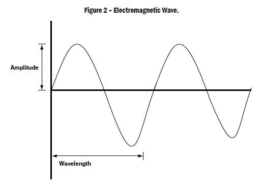
Radio communications are possible because of electromagnetic waves. There are many types of electromagnetic waves, such as heat, light, and radio energy waves. The difference between these types of waves is their frequency and their wavelength. The frequency of the wave is its rate of oscillation. One oscillation cycle per second is called one hertz (Hz). The types of electromagnetic energy can be described by a diagram showing the types as the frequency of the waves increase.
|

When describing the frequencies used by common radio systems, we use the metric system to quantify the magnitude of the frequency. A typical frequency used in fire department radio systems is 154,280,000,000 Hz. This is a frequency designated by the FCC as a mutual-aid radio channel. Dividing the frequency by the metric system prefix mega, equal to 1,000,000, this becomes 154.280 megahertz or MHz.
Land mobile radio systems are allowed to operate in portions of the radio spectrum under rules prescribed by the FCC. These portions of the spectrum are called bands, and land mobile radio systems typically operate with frequencies in the 30 MHz (VHF low), 150 MHz (VHF high), 450 MHz (UHF), 700 MHz, and 800 MHz bands.
The wavelength is the distance between two crests of the wave. The frequency and wavelength are inversely related so that, as the frequency of the wave increases, the wavelength decreases. The length of a radio antenna is related to the wavelength with which the antenna is designed to operate. In general, the higher the frequency of the waves used by the radio, the shorter the antenna on the radio.
|
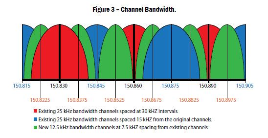
Channel Bandwidth
The radio spectrum is divided into channels. Each radio channel is designated by a frequency number that designates the center of the channel, with half of the bandwidth located on each side of the center.
Radio channel bandwidth is the amount of radio spectrum used by the signal transmitted by a radio. The greater the bandwidth, the more information can be carried by the signal in the channel. Minimum channel bandwidth typically is limited by the state of technology, and the bandwidth required to carry a given amount of information has decreased by several times over the past 50 years. However, there is a theoretical limit below which the bandwidth cannot be decreased. In addition, the actual width of a channel often is slightly greater than the minimum width, to provide some space on each side of the signal for interference protection from adjacent channels. For the purposes of radio licensing, the FCC sets the maximum and minimum bandwidth for channels in each frequency band.
The bandwidth of channels typically used in land mobile radio is measured in thousands of hertz, or kilohertz, abbreviated kHz. In an effort to place more communications activity within a limited radio spectrum, permitted bandwidth has been decreasing. Under older licensing rules, some of which are still in effect, typical channel bandwidths were 25 kHz. Newer rules require bandwidths of 12.5 kHz.
|
Radio Wave Propagation
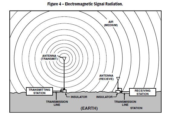
To send a radio signal from a transmitter to a receiver, the transmitter generates electromagnetic energy and sends that energy through a transmission line to an antenna. The antenna converts the energy into electromagnetic radio waves that travel at the speed of light outward from the antenna. If another antenna is located in the path of the waves, it can convert the waves back into energy and send that energy through a transmission line to a receiver.
|
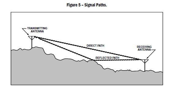
Radio signals emitted from an antenna travel both a direct path to the receiving antenna, and a path reflected from the ground or other obstacles. This reflection causes the wave to travel a longer distance than the direct wave, as shown in Figure 5.
|
The waves traveling over the reflected path then interfere with the direct waves, causing an effect know as multipath interference. Multipath interference causes a variation in the signal level at the receiver. The signal may be higher or lower than the direct signal depending on the position of the receiver’s antenna. As the antenna is moved around, the signal varies, and the user hears a signal that goes from strong and clear to weak and noisy.
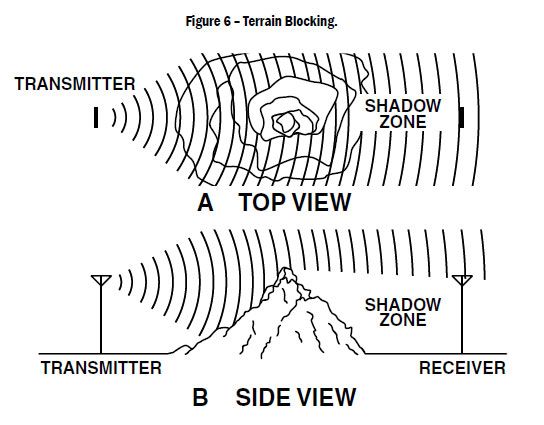
Radio waves can travel through some materials, such as glass or thin wood, but the strength is reduced due to absorption as they travel through. Materials such as metal and earth completely block the waves due to their composition and density. In addition, some materials will reflect radio waves, effectively blocking the signal to the other side.
Because buildings are built from many types of materials, the radio waves can be passed through some, be reflected by some, and be absorbed by others. This, along with the complex interior design of a building, creates a very complex environment for radio communications inside a building.
|
Interference
Radio frequency interference can be either natural or manmade. Interference from internal noise occurs naturally in all electronic equipment due to the nature of the electronic circuit itself. Manufacturers take this into account during equipment design, and obtaining a low-noise design is not particularly difficult. In addition, natural noise is produced by sunspot activity, cosmic activity, and lightning storms. This noise usually is of small magnitude and not significant for most land mobile radio communications. However, the VHF low band is affected significantly by severe sunspot activity, sometimes to the point of completely prohibiting communications.
More significant to radio communications systems is the interference produced by manmade sources. Vehicle ignitions, electric motors, high-voltage transmission lines, computers, and other equipment with microprocessors also emit radio signals that can interfere with public safety radios.
In general, manmade interference decreases with an increase in frequency. The UHF band and, initially, the 800 MHz band are much less susceptible to manmade interference than the VHF low and high bands. When systems are not subject to significant interference, they are said to be “noise limited,” in contrast to “interference limited.” The large number of transmitters used by cellular telephone companies has created intense interference in the 800 MHz band.
Although the separation of the channels allocated to cellular companies has reduced this interference, communications problems still can occur when a user is operating close to a cellular transmission facility. This type of interference is particularly a problem when the user is located near a cellular facility and the user’s radio system site is located much further away. This creates a situation called near-far interference. The user’s system signal strength is low, and the cellular signal is high, keeping the user’s radio from receiving the desired signal. The 800 MHz band always was regarded as the “cleanest” band with respect to manmade interference, and systems initially were noise limited. However all systems in the band now must be designed for maximum interference from nearby transmitters, requiring more transmitter locations and higher power creating more costly systems.
|
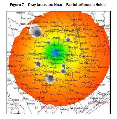
Interference from cellular transmitters is illustrated in Figure 7. The blue area in the center is the public safety transmitter and in the center of the grey areas are the cellular transmitters.
Intermodulation interference is caused directly by the mixing of two or more radio signals. The mixing most commonly occurs inside the receiver or transmitter of a radio. This mixing can create a third signal that is radiated from the antenna out to other radios. The mixing also can occur outside a radio in the transmission line or through rusty tower bolts or guy wires. Intermodulation can be difficult to identify, due to the large number of frequencies that may be present at large communications sites.
Receiver desensitization interference, also called receiver overload, is caused by nearby high-level transmitter signals that overload the initial parts of the radio’s receiver. This overload prevents the receiver from detecting the weaker desired signals, making the receiver nonfunctional. Receiver desensitization occurs near high-power radio sites, such as television and radio stations, and also can occur in poorly designed repeater systems where the transmit and receive frequencies are too close in frequency.
Several things can be done to reduce or eliminate interference. The first is the use of high-quality radio equipment. High-quality equipment has better transmitter and receiver performance that minimizes interference and reduces its effects. The use of receiver multicouplers, transmitter combiners, and repeater duplexers reduces the possibility of intermodulation and receiver overload by filtering the transmitter and receiver signals to ensure only those signals actually used by the system are passed through.
Radio system designers can reduce the possibility of their systems causing interference by selecting appropriate designs. By selecting the appropriate antenna and adjusting transmitter power levels, the system can minimize interference with other users of the same frequency. This allows more efficient use of the available radio spectrum and keeps more resources available for all users.
What Affects System Coverage?
The coverage of a radio communications system generally is described as the useful area where the system can be used reliably. Many factors affect coverage, including the radio power output, antenna height and type, and transmission line losses. However, the factor that most influences coverage is the height of the antenna above the surrounding ground and structures. By locating the antenna on a tower or mountain top, the system designer provides a more direct path from the transmitter to the receiver. In the case of one radio user transmitting directly to another radio user, having the radio antenna as high as feasible (hand held at shoulder height) significantly improves coverage.
Antennas have three major properties: operating frequency, polarization, and radiation pattern. In general, these properties apply whether the antenna is used for transmitting or receiving. The operating frequency of an antenna is the frequency at which the antenna acts as specified by its manufacturer. The antenna may operate outside its design frequency, but the performance of the antenna will be reduced.
In land mobile radio systems like those used by public safety, most antennas are vertically polarized. You can see evidence of this with the wire antennas mounted on the roofs of vehicles. Like car antennas designed for frequency modulation (FM) broadcast radio, they stick up vertically from the surface of the vehicle.
The radiation pattern of the antenna is the shape of the relative strength of the electromagnetic signal emitted by the antenna, and this depends on the shape of the antenna. The radiation pattern can be adjusted through antenna selection to provide coverage where desired and to minimize coverage (and, in turn, interference) in undesired directions.
Fixed-Site Antennas
Fixed-site antennas are mounted on towers or buildings to provide the dispatch or repeater coverage throughout the service area. The antennas used must be designed to operate in the system’s frequency band and, for best power coupling, should have a center frequency as close as possible to the actual operating frequency.
|
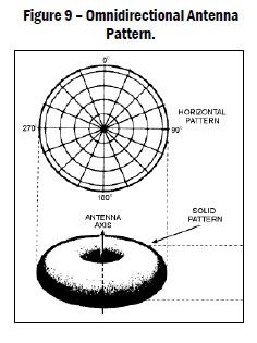
The radiation pattern for the antenna should be selected to provide a signal in the desired sections of the coverage area, and have minimal coverage outside the desired coverage area. This will help ensure that the system is not interfering with other systems unnecessarily. The most basic practical antennas are omni-directional, and have approximately equal coverage for 360 degrees around the antenna.
However, as shown in Figure 9, the antenna pattern is more like a slightly flattened donut. This causes an area immediately under the antenna to have lower signal strength, and less coverage, than farther away from the antenna.
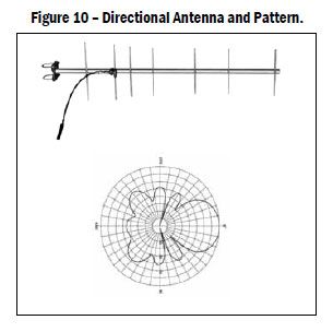
Directional antennas are used to direct the signal toward the users and away from unwanted areas. The antenna is said to have gain over an omnidirectional antenna in the direction of highest signal. Figure 10 shows a directional antenna called a Yagi, along with its radiation pattern looking down on the antenna. The pattern shows a stronger signal from the front of the antenna and a weaker signal from the back. The signal strength protrusions behind the main signal are called lobes and, in most cases, antenna designers strive to minimize this unintended signal.
|
|
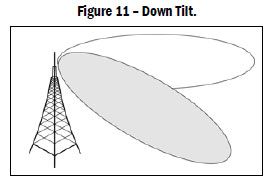
When an antenna is located on top of a mountain or tall building, the coverage loss created by the “hole” in the radiation donut may have a significant impact on coverage in the area immediately around the antenna. To compensate for this, a directional antenna can be tilted slightly to direct more of the signal downward, as shown in Figure 11. This tilting is known as mechanical down-tilt and increases the energy immediately below the antenna while reducing the maximum distance the signal will travel. Unfortunately, when using an omni-directional antenna, tilting the antenna down in one direction results in tilting the pattern up on the opposite side of the antenna. For this reason, special antennas with electrical down-tilt are used when omnidirectional coverage is required, such as on a tall building in the center of the coverage area.
Mobile and Portable Antennas
In general, all mobile and portable radio antennas are omnidirectional to provide coverage 360 degrees around the radio user.
Vehicle antennas should be mounted so that they are not obstructed by equipment mounted on the top of the vehicle. Light bars, air conditioning units, and master-stream appliances are some typical obstructions found on fire service vehicles. Some obstructions, such as aerial ladders on truck companies, cannot be avoided, and the designer must select the best compromise location.
Vehicle antennas mounted on the roof of fire apparatus can be damaged by overhead doors, trees, and other obstructions. Ruggedized low-profile antennas often are a better choice, even if they have a lower gain than a normal whip antenna. A properly mounted intact antenna with a lower gain is much better than a damaged antenna of any type.
|
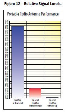
Portable antennas usually are provided by the portable radio manufacturer and are matched to the radio. In some cases alternative antennas can be selected for the radio to overcome specific user conditions.
When a portable radio is worn at waist level, such as with a belt clip or holster, the user’s body absorbs some of the signal transmitted or received by the radio. In addition, the antenna is at a much lower level than if the user were holding the radio to his or her face for transmitting.
Since the radio system is designed for use with the antenna oriented vertically, the performance of the radio is reduced when the antenna is horizontal. This is particularly important for firefighters, since the radio they use may become oriented horizontally when they are crawling low inside a structure fire.
Summary
Radio communication takes place using electromagnetic waves that travel from the transmitter to the receiver. These waves can be reflected or absorbed by materials such as buildings, the earth, or trees, reducing the strength of the wave when it reaches the receiving antenna. Elevating the transmitting or receiving antenna will reduce the likelihood of the wave being affected by buildings or trees, because the path to the receiver will be more direct.
Interference from undesired radio waves is always a possibility in a radio system. The potential for natural interference decreases as the frequency band increases, but manmade interference is very high in the 800 MHz band due to the proximity of cellular and other non-public safety communications systems. This interference can make it difficult to communicate effectively in the presence of the interference.
When designing radio communications systems, the designers must take into account the presence of reflecting or absorbing materials and interference. This may require constructing taller towers to support the antennas or increasing the power of the transmitters to overcome the loss of signal strength and interference. The system design must take into account local terrain, trees, buildings, and the density of interference-generating sources.
NEXT SECTION - Radios and radio systems